LumiMonitor
Entry12: 11/26/2019
The presentation is due today. The powerpoint file has been uploaded into the repository and can be found here.
Entry11: 11/22/2019
Finishing up the documentation of the project. I have updated the final budget of the project along with the associated receipts. Unfortunately, I was not able to get a refund on the initial Raspberry Pi 3 purchase, so that is a cost that I will absorb. Financially, it has cost me a total of $247.96CAD, compared to the initial figure of $81.89CAD.
I am on track of my schedule, despite falling behind during the middle of the project. Currently preparing for my presentation on November 25. Afterwards, I will be working on the build order of my project.
Entry10: 11/19/2019
I have worked on finding an enclosure for my project this week to encase the RP4, PCB, and sensor. I have found a suitable case online and printed it in the prototype lab. I have uploaded the CorelDraw .cdr File in the project repository; this is the enclosure design:
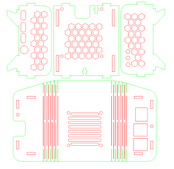
The design allows for the raspberry pi ports to have an opening, allows for easy access to the SD card slot, and plently of holes in the design to properly ventilate the project. I went to the prototype lab to have the design cut with assistance from Professor Kelly Gray.
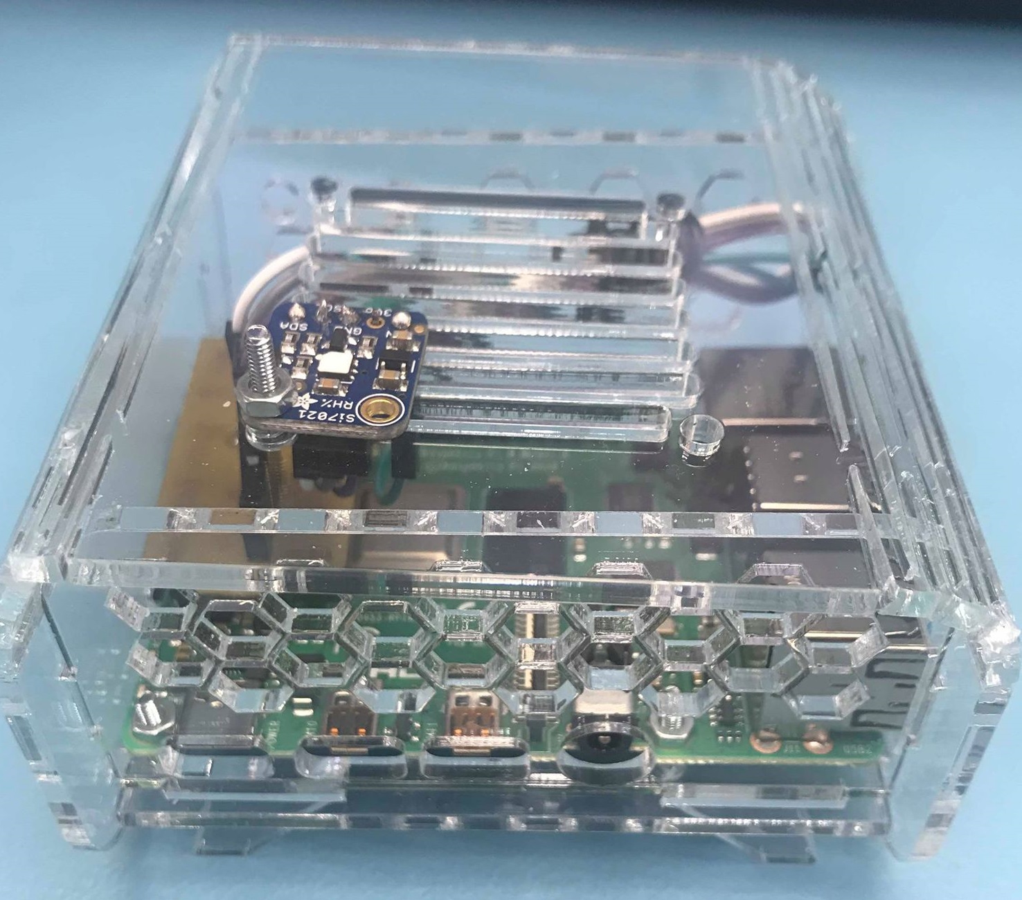
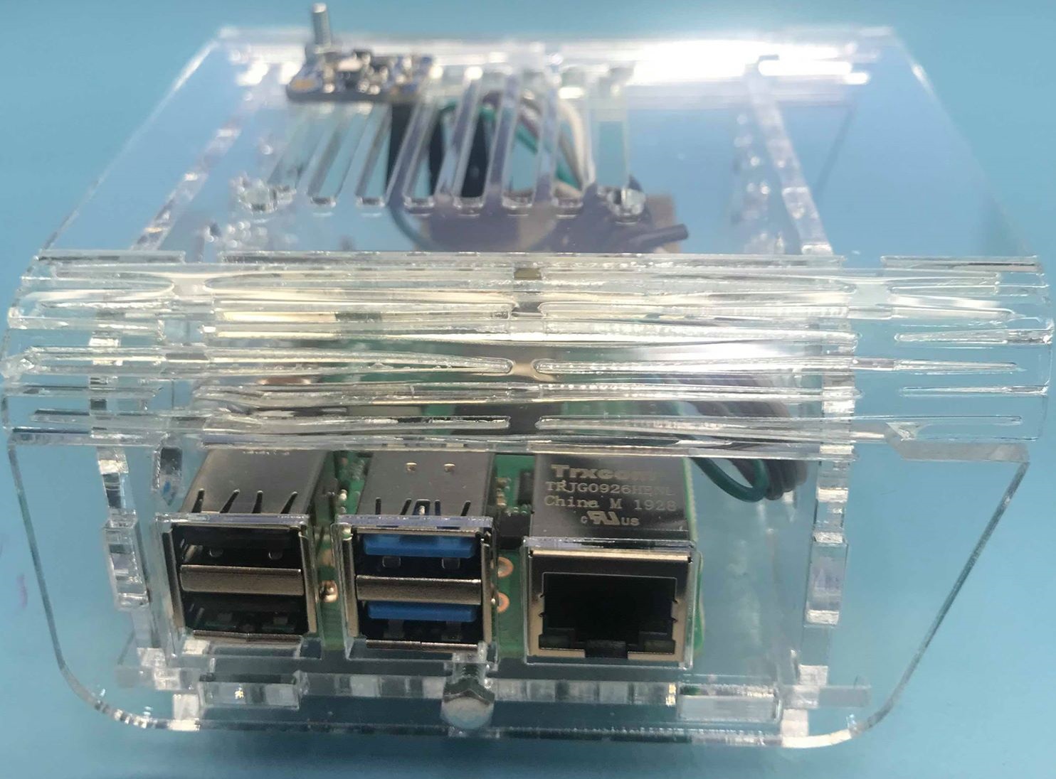
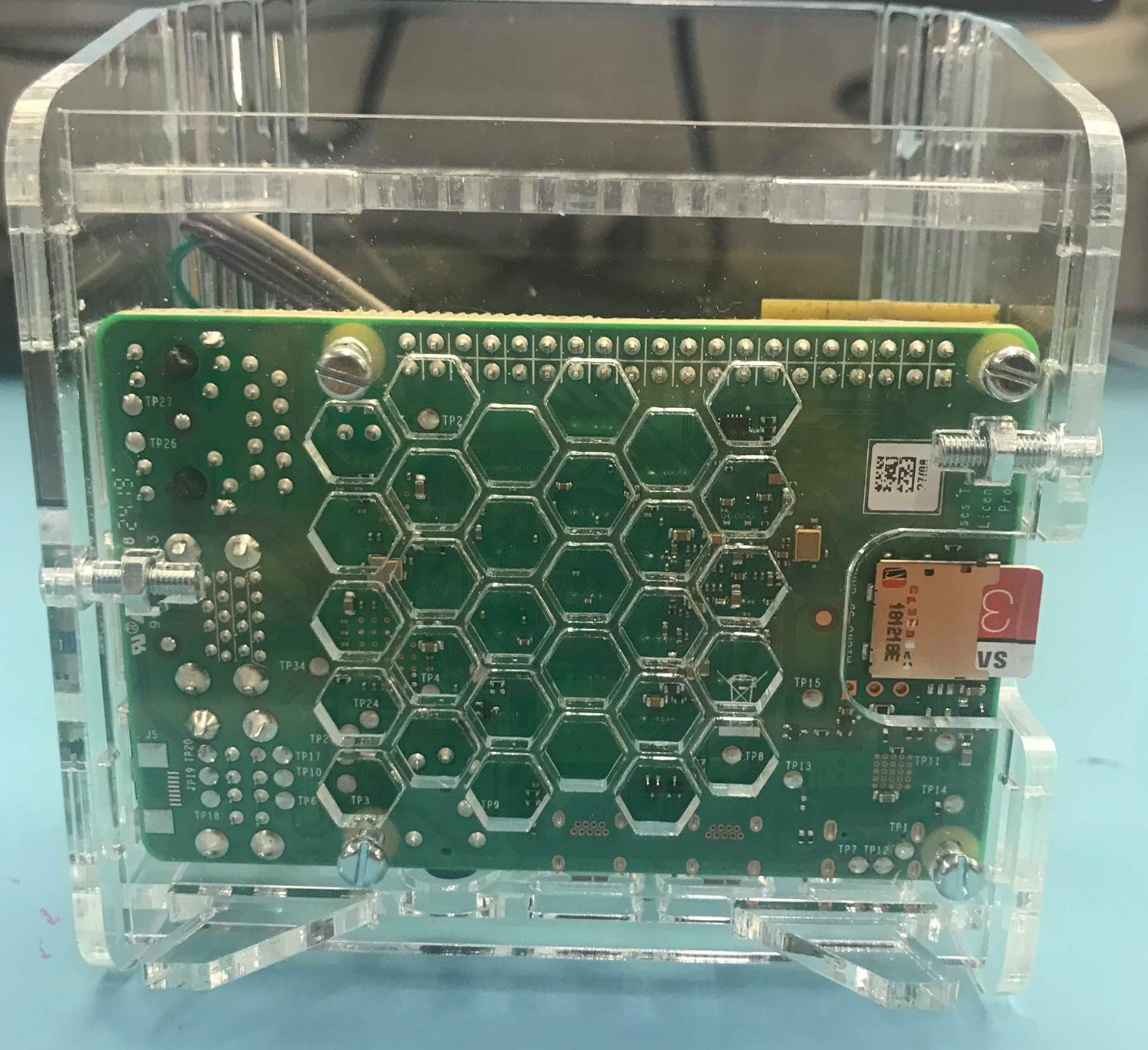
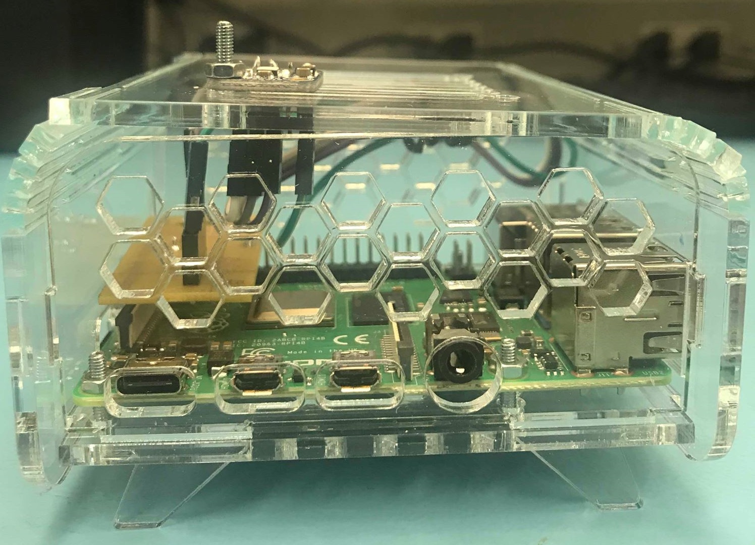
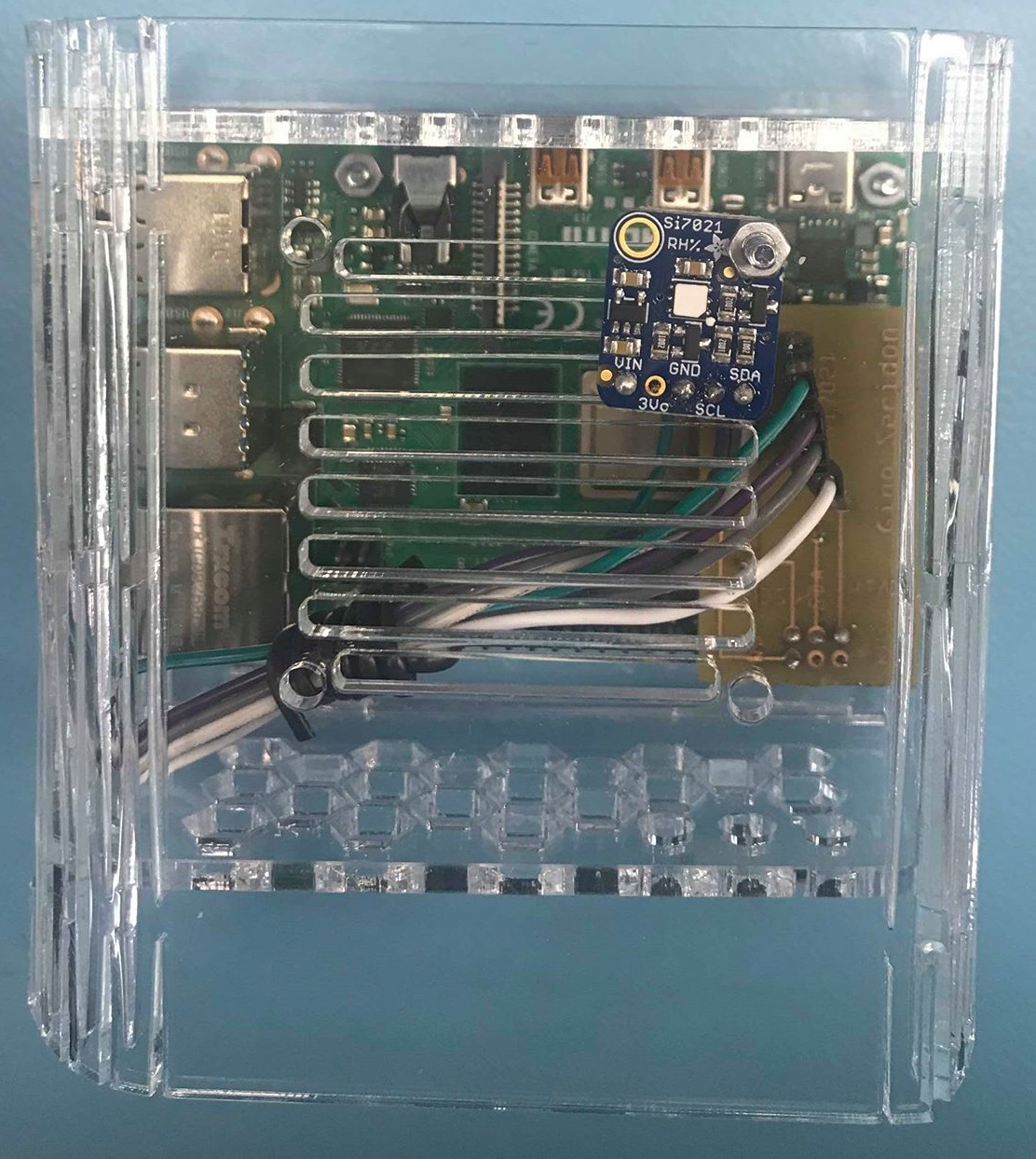
After laser-cutting the design, I initially intended the sensor to be attached to the PCB, to remove unnecessary wiring. However, after testing the sensor in the enclosure, I have found that when the raspberry pi heats up, it affects the temperature readings of the sensor. Even with all the ventilation holes, the sensor would still be too close to the raspberry pi. Ultimately, I have decided to move the sensor outside of the case, connected to the PCB through wires, and the sensor is secured onto the case using a screw. With the sensor being outside of the case, it will no longer be affected by the heating hardware and it will be more able to accurately measure the temperature and humidity of the surroundings. Here are some photos of the finished, assembled design:
Entry09: 11/08/2019
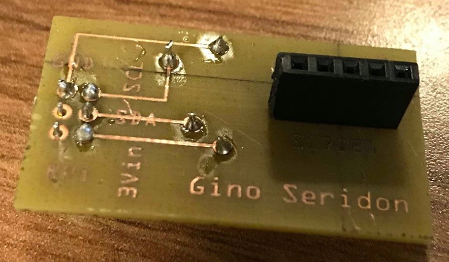
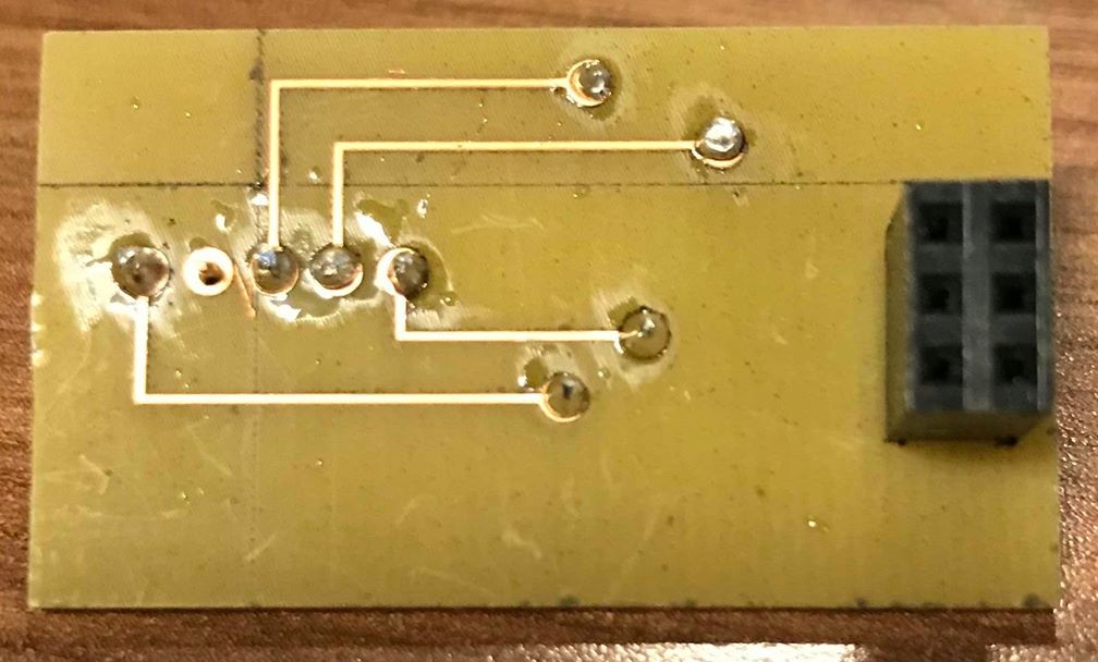
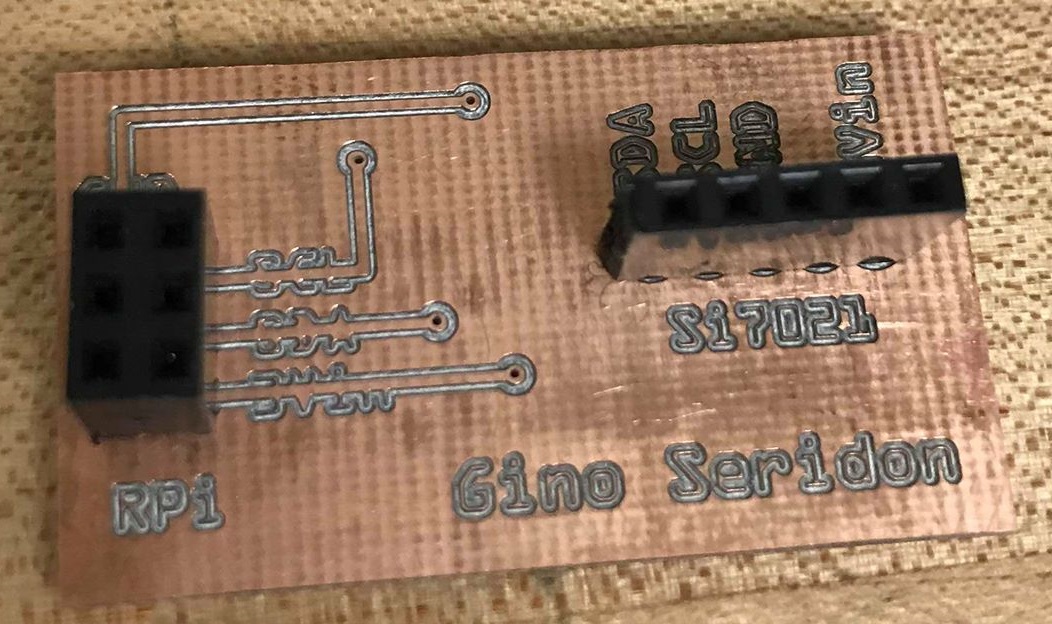
I have completely remade the PCB because it was not correctly soldered the headers and it was not powering up properly with the pi, hence I was not able to do an in class demo. I have uploaded an updated version of the Fritzing File for this new PCB; the main change that I have made is a bigger via and thinner wires. The headers are then soldered in the proper position and can now be mounted directly onto the raspberry pi. Here is the new soldered PCB views (frontside and backside):
The PCB fits nicely on top of the raspberry pi now and is directly connected, removing the need for wires:
I have also uploaded a video demo here to demonstrate that the pi is receiving information from the sensor through the soldered PCB.
Financial status is the same as last week; the refund is currently being processed and Amazon will inform me of any updates.
Moving forward, I am currently working on the design for the casing of the raspberry pi. Since the PCB is mounted directly on the pi, I would need to design a case for the RP4 with an opening at the top to allow the sensor to evaluate the temperature and humidity. I will be getting this design printed by next week Monday.
Entry08: 11/08/2019
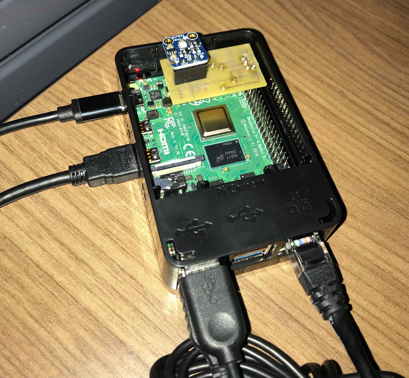
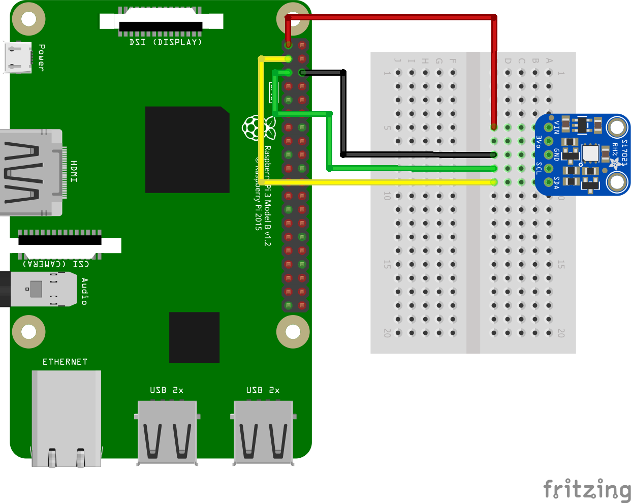
As of today, I have caught up with my project schedule. I have received my newly purchased Raspberry Pi 4 on Sunday, November 3rd and have had no problems setting up the operating system and additional upgrades for the coding environment. I have been able to properly assemble my breadboard with the si7021 temperature/humidity sensor and connected them both to the RP4 (as shown below), marking my breadboard milestone for this project.
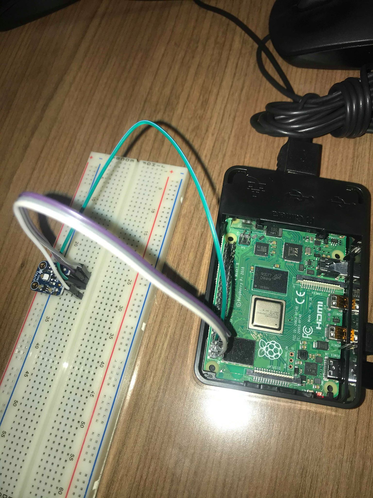
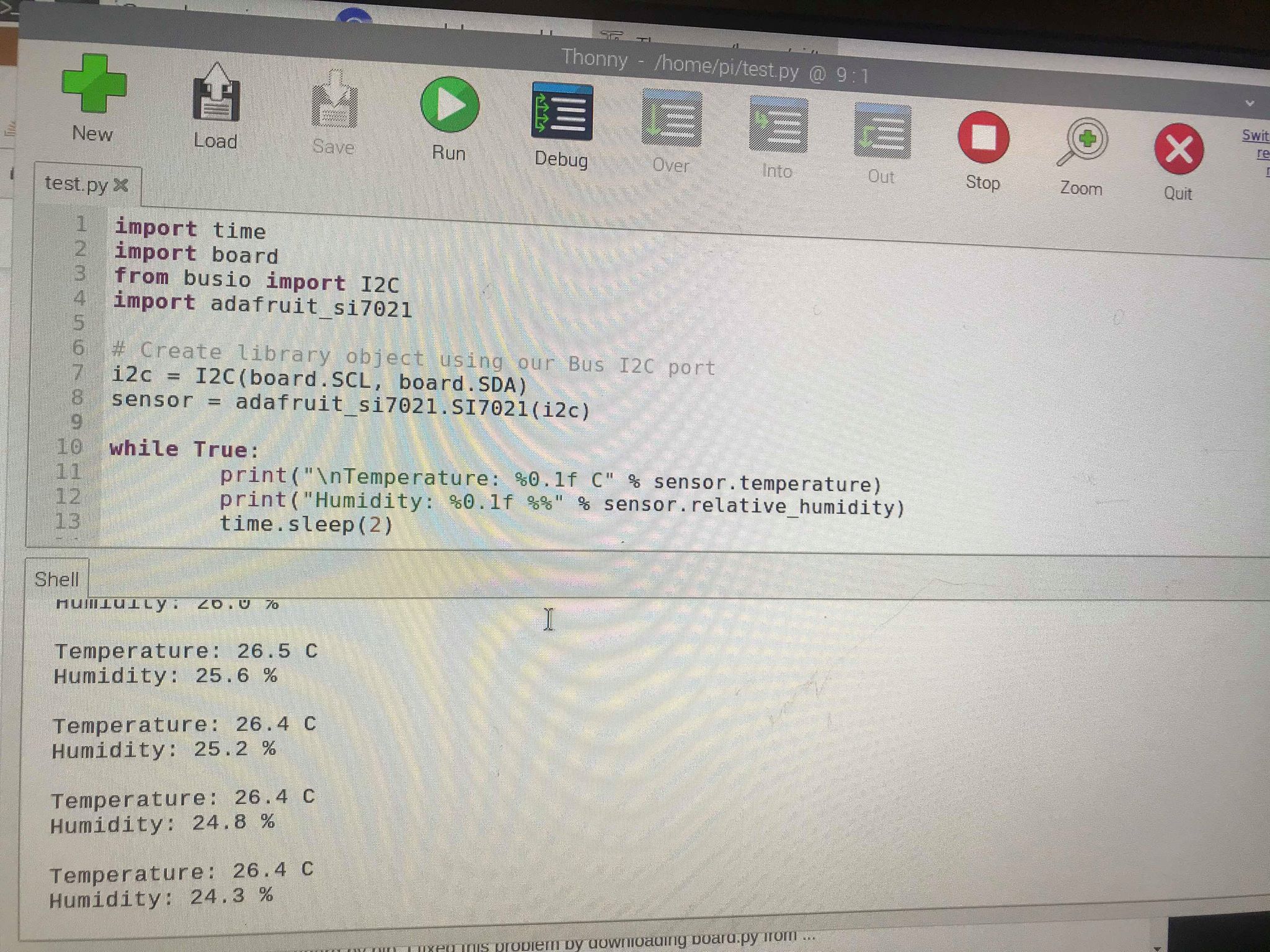
The code that I am using from adafruit works properly with the RP4 and sensor, and it is displaying the proper temperature and humidity readings from the sensor.
I have picked up my Printed Circuit Board a couple of weeks ago after submitting my design to the prototype lab, and I have soldered it with headers to allow wires to connect to the board:
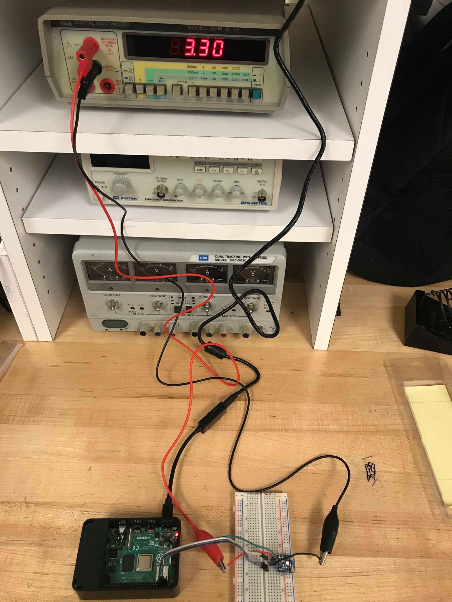
To test the circuit of the sensor, breadboard, and PCB, I have connected them to a voltmeter to verify the correct voltage. Recall that this sensor uses 3 VDC. The image below shows that the correct voltage of ~3V is being shown when the RP4 is connected to the sensor via breadboard:
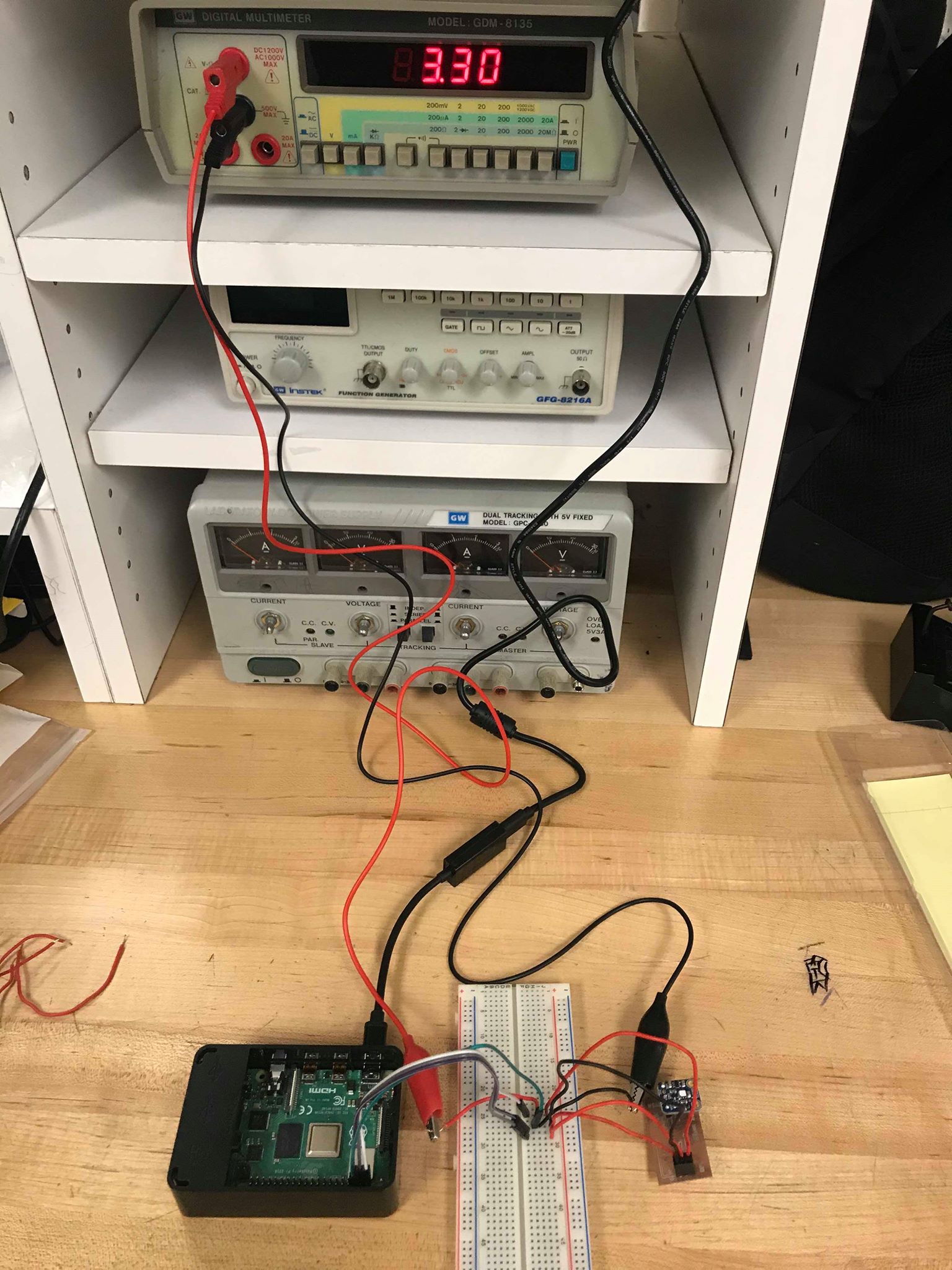
The image below shows that the correct voltage of ~3V is being shown when the RP4 is connected to the sensor via PCB (and using the breadboard as a way to connect the voltmeter):
With these being completed, I am officially on schedule for next week, despite being set back over two weeks due to complications with the raspberry pi.
Financially, I have spent over three times the amount that I initially started with. My initial purchase consisted of $81.89CAD, but with complications with the Raspberry Pi 3 and burning of SD cards, I have spent an additional $166.07CAD in the past week, bringing the total cost to $247.96CAD. I am still in the process of trying to get a refund on the RP3 that I have initially purchase, which could bring down the amount spent below $200. I will post updates on this situation when the refund goes through.
The only other problem that I have encountered after receiving the RP4 is that I cannot seem to connect the pi to my home internet network. This severely limited the amount of time that I have been able to work on this project, needing to contantly travel on campus after class hours to work on. However, despite all the complications and headaches, I’m right on schedule for the following week.
Entry07: 11/01/2019
I’m having a lot of problems with the Raspberry Pi at the moment, and it is severely delaying my progress with the course. I have set up an OS for the pi during the break, but the pi heats up extremely quickly within the first few minutes of being powered up. The microSD card that I was using for the pi burned out a few days ago as well. This pressured me to purchase another SD card last minute, which did not arrive until Wednesday of this week. This new SD card was also uploaded with the operating system, which the balenaEtcher is verifying to be acceptable to use. However, when I try to install the operating system now, the raspberry pi would still heat up very quickly, and it would show an error on the screen. I have tried several times to reupload the operating system into the SD card, each time the disk imager would verify that the loading was successful (I even used a different SD card from a friend on different attempts). But the same thing occurs, the raspberry pi would continuously show an error and stopping me from installing the operating system, thus halting my progress on the assignment.
I’m considering on just purchasing the new Raspberry Pi 4, as I suspect that the Raspberry Pi 3 that I have purchase is faulty and corrupting the SD cards that I use for it. I will be purchasing the Raspberry Pi 4 this weekend and hope that it will arrive quickly, so that I can set up operating system once more and run the code for the si7021 temperature/humidity sensor.
Financial wise, things have taken a turn for the worse. While I will be attempting to refund the Raspberry Pi 3, I have purchased a micro SD card in the process of troubleshooting my problems with the Pi. I will also be looking to purchase the complete set of the Raspberry Pi 4 for this weekend in hopes that I will be able to catch up with my schedule.
This week’s purchases:
- MicroSD card: $11.97 CAD + $1.56, free shipping
- Raspberry Pi 4: $134.99 CAD + $17.55 tax, free shipping
Schedule-wise, I am a behind on loading the operating system and the breadboard milestone, as I have not been able to get the RP3 to work properly. This puts me approximately two weeks behind schedule. However, if I should get the new RP4 by this weekend, I will be attempting to catch up on installing the OS and connecting the sensor to the breadboard by next week. If all goes well, I will be able to get back on schedule.
I have found the code for the si7021 temperature/humidity sensor as well, and will be attempting to use this code to test the sensor when the RP4 has arrived and set up properly. It is uploaded here.
Entry06: 10/15/2019
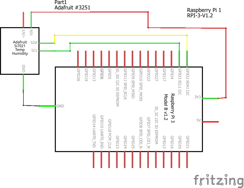
The schematic of the sensor and raspberry pi:
The breadboard connection:
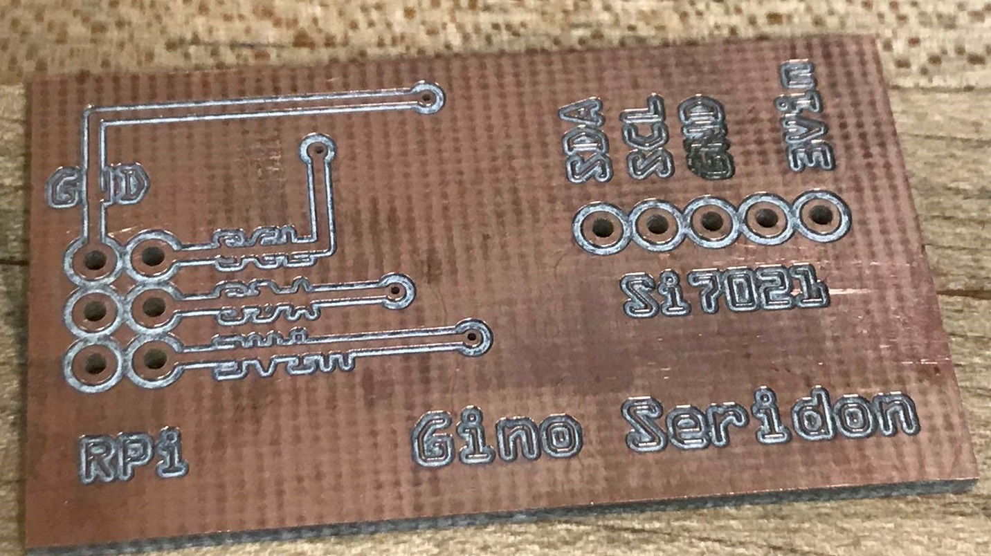
The PCB design:
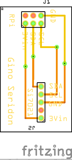
The design of the board was fairly simple. Vin is the power pin, and it is connected to the 3 VDC pin on the raspberry pi. The sensor’s 3v3 pin is not used. The GND pin is the common ground for the power and logic. The SCL pin is the I2C clock pin, which is connected to the raspberry pi’s I2C clock line. The SDA pin is the I2C data pin, which is connected to the raspberry pi’s I2C data line. These pins are represented by headers instead of the actual sensor/raspberry pi; the 5 pin header is for the temperature/humidity sensor, while the 6 pin header is for the raspberry pi.
As of today, I am right on time according to my schedule. I have the breadboard, schematic, and PCB designed, and it is ready to be printed. I will be sending the gerber files to the prototype lab to have my PCB created. I had a few problems with my initial design of the PCB, but after attending the class session and getting some feedback from Professor Medri, I was able to correctly redesign my PCB.
Over this past weekend, I had to re-order my Raspberry Pi as the parcel has been lost in the mail and could not be retrieved. Amazon was able to resend my purchase, and I have acquired the Raspberry Pi and the sensor by Sunday, October 13. There were no additional charges to this transaction, so I am on track with my financial status. All the images (schematic, PCB, breadboard) and files (FZZ file using the pi and without it) regarding the hardware of the project has been uploaded into my repository, with the appropriate links in the blog post:
The two fritzing files; one with the raspberry pi, and one without it (just for the PCB design): With Pi, Without Pi
Entry05: 09/29/2019
I have placed my order for the Raspberry Pi, the webcam, and the temperature sensor. I have also updated the project budget to include the additional purchase of the Raspberry Pi.
Proof of Purchase: Amazon, Digikey
Entry04: 09/24/2019
Today my group members and I had our meeting with our collaborator, running our ideas through him and getting some feedback from him. He was very enthusiastic towards our ideas and offers his full support to the direction of our project.
I have uploaded the project budget for the LumiMonitor’s temperature sensor, with the webcam price included.
Link: Project Budget PFD
Entry03: 09/10/2019
Submission of the hard copy printout of the project proposal. I have completed a project schedule in the form of a gantt chart and have converted it into a PDF. This version of the schedule is uploaded into the repository and can be found here.
This schedule is based off the due dates outlined in the CENG317 Course Repository.
Entry02: 09/09/2019
Completed the proposal content and the project proposal, and converted them into a PDF file. These files, along with the Excel proposal sheet, are uploaded to my online repository, in the “Documentation” folder. I have also completed creating all the different folders needed in the repository today, leaving a note in each folder to dictate the folder’s future content.
The links for the uploaded documents are as follows:
Lastly, I have activated the github master branch for the repository, enabling me to publish the repository website.
Link: https://gseridon.github.io/LumiMonitor
Entry01: 09/05/2019
First day working on the Lumi Monitor project. I did a bit of research for the project to try and brainstorm some ideas for it. I have created a repository today, as well as having completed my registration along with my group members on Riipen. I’m filling out the proposal with content pretaining to the Lumi monitor and will be uploading the finished documents on github.